Your laptop has no sound. You have updated the drivers, reinstalled Windows, checked BIOS settings — and nothing works. The device is simply not detected. That is when board-level repair technicians start looking at the audio codec IC — most commonly a Realtek ALC-series chip on the motherboard.
Realtek makes chips for multiple laptop functions — audio, LAN, card readers, USB-C/PD controllers. But in repair work, the most commonly replaced one is the Realtek audio codec. This is the chip responsible for all audio functions on your laptop. When it fails, sound disappears completely — and no software fix can bring it back.
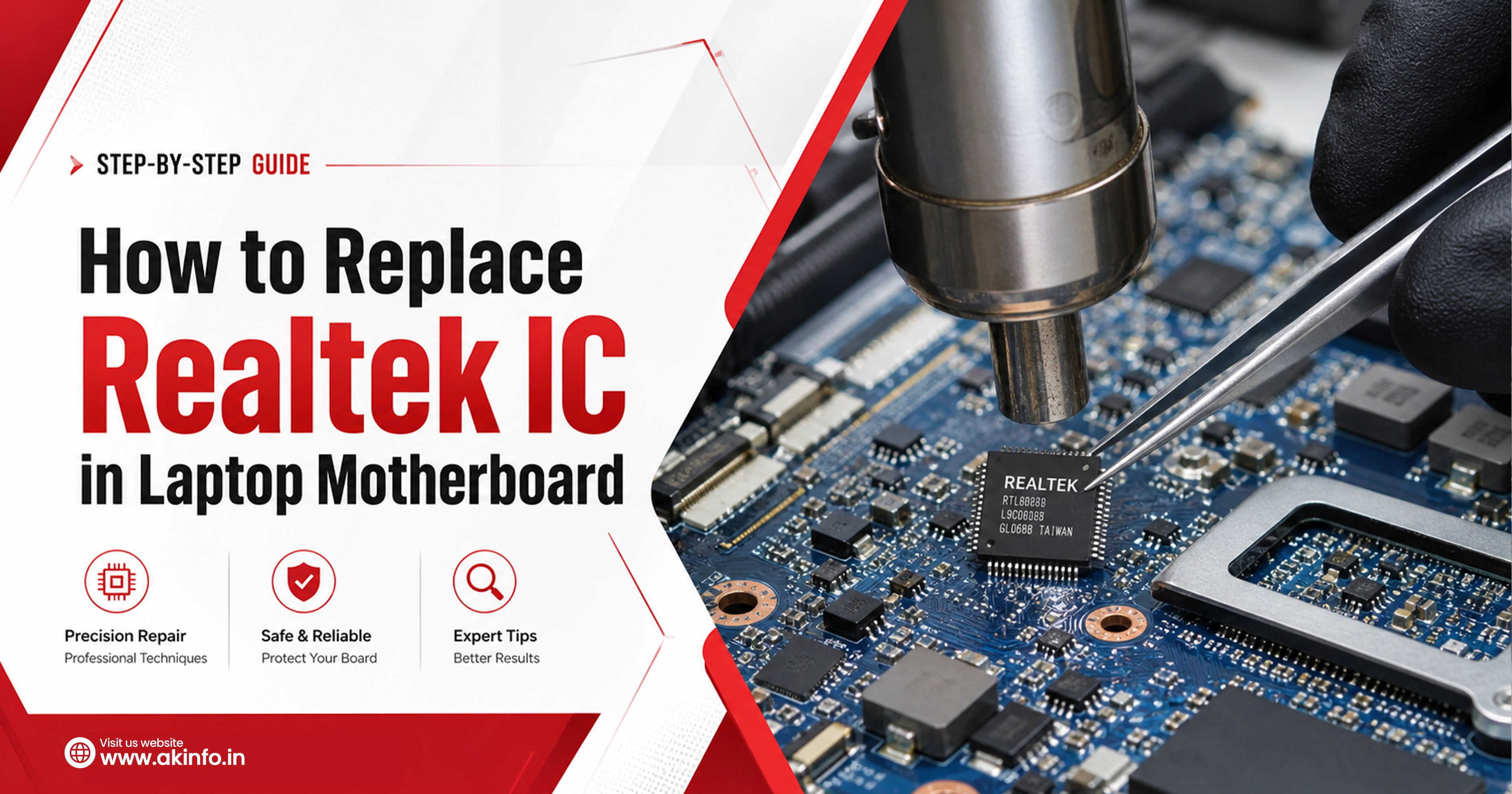
This guide explains how to replace a Realtek audio IC in a laptop motherboard, from diagnosis to post-repair testing. Also, here we’ll cover the full process: how to confirm the fault, what tools you need, the step-by-step replacement process, common mistakes, and what to do if the audio still does not work after replacement.
What Is a Realtek IC in a Laptop Motherboard?
Realtek Semiconductor makes controller chips used in most modern laptops. On a motherboard, you may find Realtek chips handling audio (ALC-series), LAN (RTL-series), card readers, or USB-C power delivery depending on the design. In board repair, when technicians say 'Realtek IC', they almost always mean the audio codec — typically an ALC256, ALC3246, ALC269, or similar small QFN/BGA package chip. The chip number and its exact function depend on the laptop model and motherboard schematic.
Common Signs of a Faulty Realtek IC
Before touching the board, identify the symptoms clearly. These are the most common signs of a faulty Realtek audio IC:
- No sound from speakers complete silence even at max volume
- Headphone jack not working
- Sound device not detected
- Distorted audio crackling, static, or very low output
- Intermittent audio after board repair
- Heat or short near the chip area
Tools Required for Realtek IC Replacement
Board-level IC replacement is precision work. Using the wrong tools leads to pad damage and a permanently dead board. Here is what you need:
- Hot air rework station
- Soldering iron
- Isopropyl alcohol
- Digital microscope
- Boardview software
- Verified new chip- in case of an old chip needs to be replaced
- And other small tools like a solder wick, tweezers, aluminium foil and flux
Important Checks Before Removing the Realtek IC
Before you apply any heat, do these checks. Skipping any one of them can cost you a board.
- Confirm exact chip number and package: Read the chip marking under magnification — e.g., ALC256, ALC3246. Verify package type (QFN, BGA) and pin count
- Check donor/new chip compatibility: The replacement must match the original exactly — same chip number, same package, same revision if possible
- Inspect board for corrosion or missing pads: If liquid damage is involved, check pad condition before removing the chip — some boards need pad repair before replacement can succeed
- Protect nearby plastic connectors and small components: Cover LCD connector, keyboard connector, and battery connector with Kapton tape — they will be damaged if hot air drifts
- Note chip orientation and pin 1 marking: Photograph the original chip before removal — the pin 1 dot or marker must be correctly matched on the replacement.
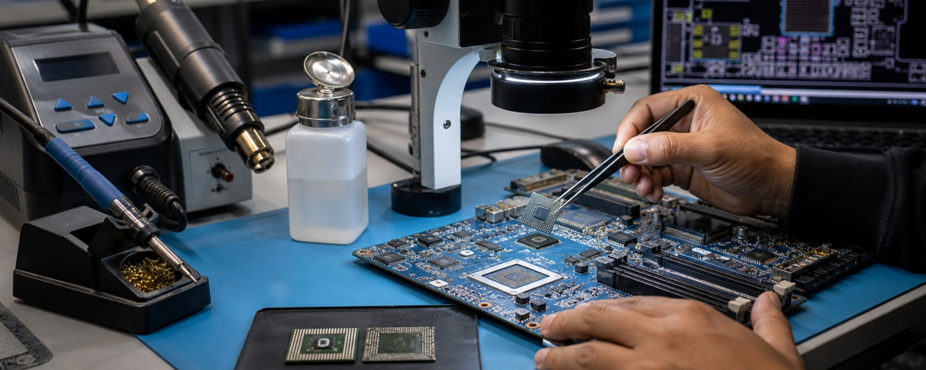
Step-by-Step Process to Replace Realtek IC in Laptop Motherboard
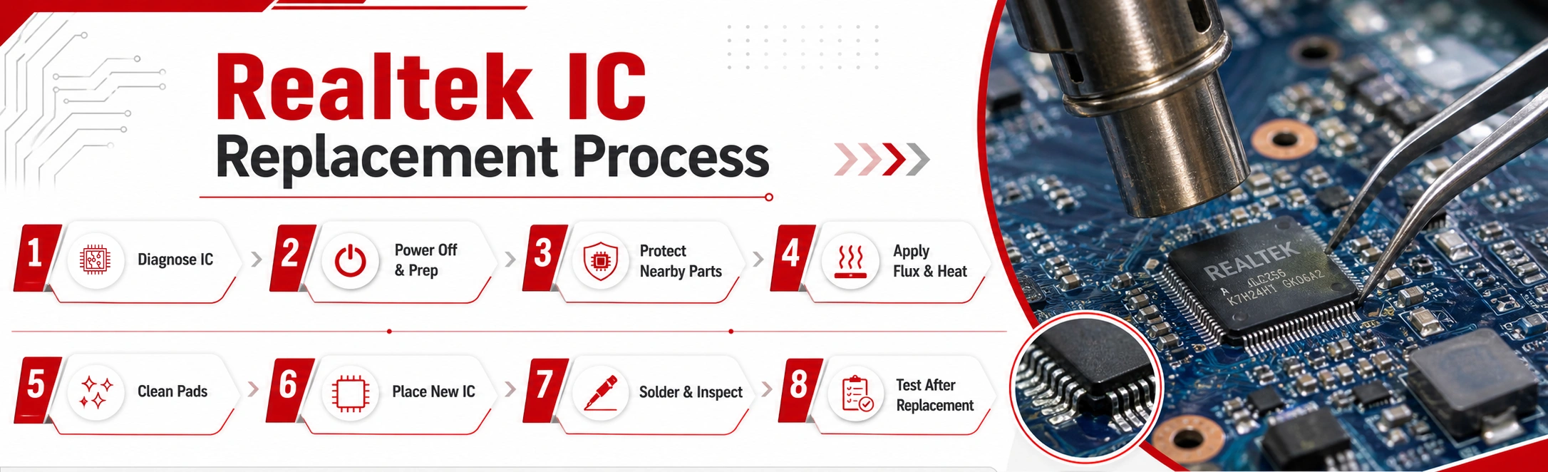
This is the core rework procedure. Follow each step in order. Do not rush — rushing microsoldering jobs always causes pad lifts, bridges, or misalignment. Each step below reflects the standard process used in professional laptop motherboard audio IC repair work.
Step 1: Diagnose Before Replacing the Realtek IC
Replacing the chip is the last step, not the first. Many repair technicians lose time replacing a perfectly fine chip. Do this first:
- Rule out driver and software issues — test with a clean OS install or live USB.
- Check BIOS-level audio behaviour — if the audio device appears in BIOS setup, the codec is alive and the issue is software or OS-side
- Inspect surrounding passive components — capacitors and resistors near the codec can fail independently.
- Confirm power rails and enable signals — check that the codec is receiving correct supply voltages or not.
- Compare with schematic/boardview — use the board schematic to trace audio lines.
- Verify if the fault is in chip or other hardware issue
Step 2: Remove Power and Prepare the Board
Once you’re done with the diagnose part:
- Disconnect battery and charger
- Remove the motherboard from the chassis because fully accessible boards are safer to rework
- Secure the board on a PCB holder or workbench with thermal mat — it should not move during hot air work
Step 3: Shield Nearby Components
- Cover all plastic connectors — LCD, keyboard, battery, USB ports with Kapton tape or aluminium foil
- Shield nearby ICs if hot air will get close — VRM, EC, and other small chips can be damaged by misdirected heat
Take a photo of the board before you start — you will need this if anything looks different after the work
Step 4: Apply Flux and Heat the Faulty IC
- Apply no-clean flux around the chip perimeter — good flux coverage makes solder release clean
- Set hot air to 350–370°C with medium-low airflow — the exact setting depends on your station and chip package
- Move the nozzle in small circles over the chip — do not hold it still. Heat the chip evenly from above
- Lift the chip only when solder has fully released — the IC should lift off with zero resistance. Never force it
Clean the Pads Properly
- Remove old solder using desoldering wick and a clean iron tip — remove all visible solder from the pads
- Inspect for lifted pads or damaged traces — use the microscope. Any lifted pad needs jumper repair before the new chip goes on
- Clean the area with IPA 99% and a soft brush — the pads must be shiny, flat, and completely clean before new chip placement
Step 6: Place the New Realtek IC Correctly
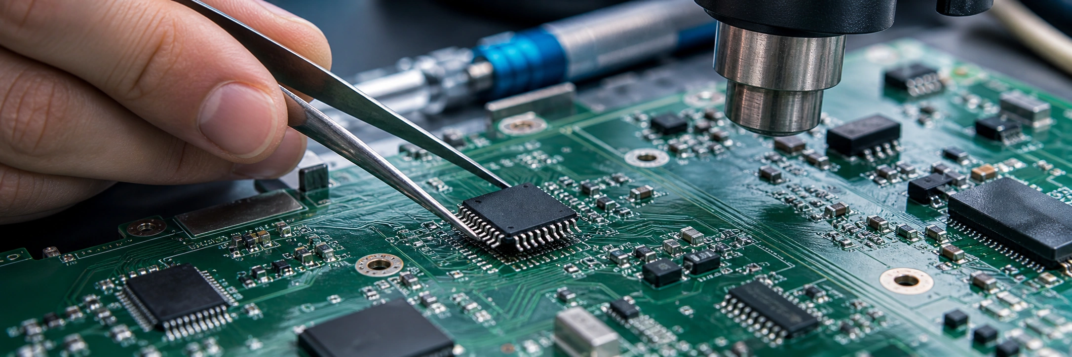
- Align pin 1 — match the dot or marker on the new chip to the board's pin 1 indicator (check your photo and the schematic)
- Centre the chip on the pads under the microscope — all pads should be visible and aligned with chip pins
- Tack one corner to hold position before full reflow — a brief touch with a fine iron tip is sufficient
Step 7: Solder and Inspect the IC
- Reflow with hot air at the same settings — apply flux first, then heat until solder wets to all pads cleanly
- Inspect under magnification — check for bridges (solder joining adjacent pins), cold joints (dull appearance), and misalignment
- Touch up any issue with a fine-tip iron and fresh flux before moving on — one cold joint can cause intermittent failure
Step 8: Test the Board After Replacement
- Continuity checks first — verify no short to ground on power rails. Use multimeter in diode mode across supply pins
- Power-on test — connect external power only (no battery). Check that the board powers on without current spikes
- Verify device detection — connect to OS and check if audio codec appears in Device Manager
- Verify actual function — play audio from speakers and test headphone jack. Check all audio paths that the codec handles
Technician Note:
In professional laptop repair training, students learn that a board-level audio fault is often not caused by a faulty Realtek IC. In many cases, the issue is related to coupling capacitors, missing power rails, or BIOS/software faults.
Start Your Career in Chip-Level Laptop Repair Today!
Join AK Info Laptop Repairing Course and turn your interest in gadgets into a professional skill. Learn practical motherboard-level repair, fault diagnosis, and troubleshooting with hands-on training. Build strong technical skills and confidence for a successful career in laptop repair.
Call Now! →Limited seats available – Enrol now and start your repair career!
Common Mistakes to Avoid During Realtek IC Replacement
Avoid these mistakes they can cost Boards:
- Replacing the chip without confirming the fault — wasted effort and risk if the problem is software, a passive component, or a missing power rail
- Overheating the board — holding hot air on one spot too long warps PCB layers and damages nearby components permanently
- Lifting pads — forcing chip removal before solder has fully melted, or using excessive heat, tears pads off the board
- Using the wrong replacement part — can cause non-detection or partial function
- Poor alignment — a chip off-centre by even 0.1–0.2mm on a fine-pitch QFN causes multiple solder bridges
- Not checking surrounding capacitors/resistors
What to Check If the New Realtek IC Still Does Not Work
New chip installed but audio still missing? Work through this checklist before considering the board a loss:
- Check driver and device detection — clean OS install. If device still not in Device Manager, the issue is hardware, not software
- BIOS update or firmware — some laptops need a BIOS update after audio codec replacement.
- Verify power rail — measure the codec's supply voltage against schematic.
- Inspect for damaged traces — use continuity mode on multimeter to trace each audio line from codec to connectors.
- Check for wrong chip version — some ALC-series chips look identical but have different internal configurations.
- EC/BIOS interaction — on some platforms, the embedded controller (EC) or BIOS has a stored state that must be cleared after hardware changes
- Recheck solder joints under microscope before assembling the device
Conclusion
Successful Realtek IC replacement is not just about swapping one chip for another. It starts with a correct diagnosis — ruling out software, missing rails, and passive component faults before any heat is applied. It requires the right tools, the right replacement part, careful rework, and thorough testing after the job is done.
The chip replacement itself is just one part of the board repair process. The diagnosis before it and the verification after it are equally important. A well-executed replacement with full post-repair testing is the difference between a reliable result and a board that fails again in two weeks.